

Cable Abrasion Prevention Starts at Contact Points
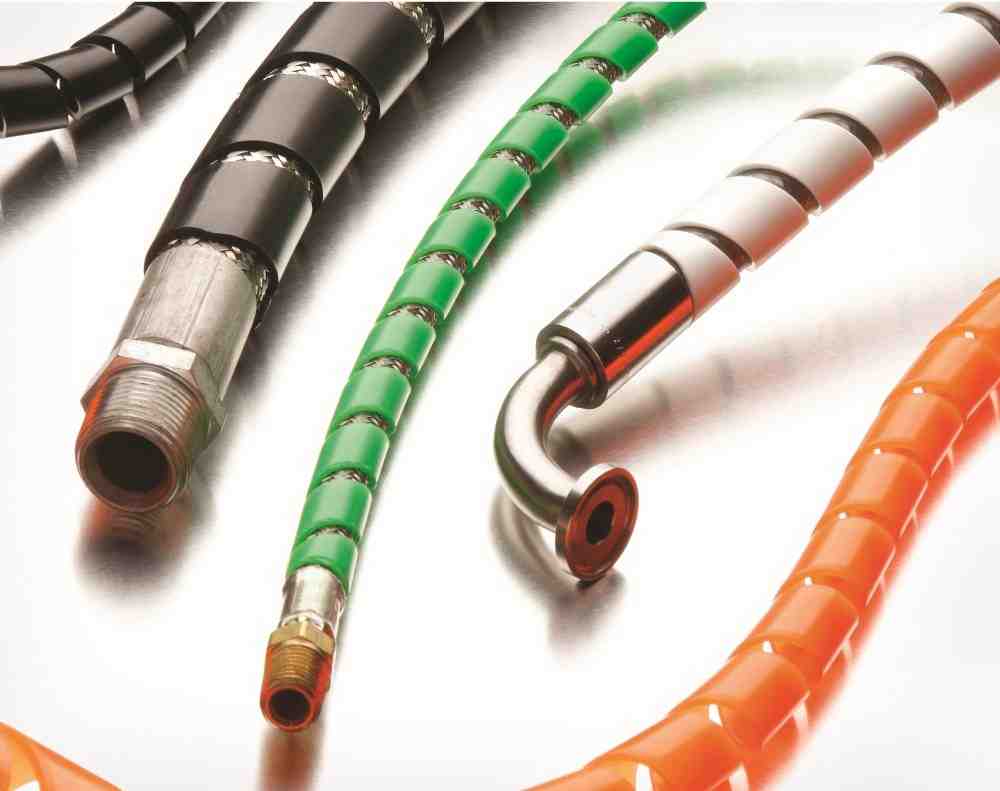
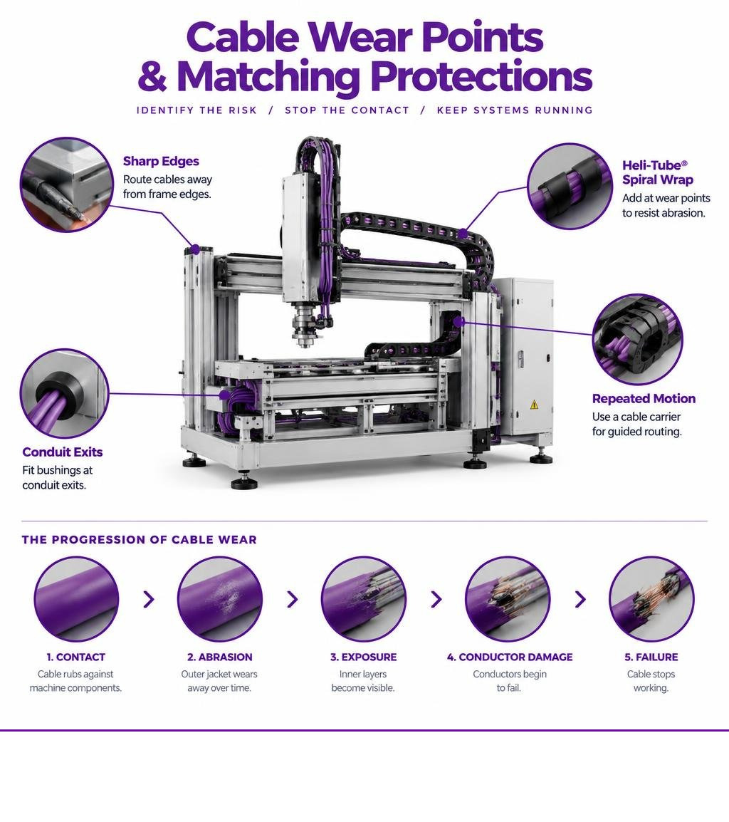
To prevent cable abrasion, find where cables rub, then stop the contact. Route cables away from sharp frame edges, fit bushings at conduit exits, and secure runs so they cannot scrape nearby parts. Add Heli-Tube® spiral wrap at wear points, and use a cable carrier where repeated machine motion calls for guided routing. Inspect the outer jacket regularly and address wear before conductors are exposed.
On industrial machinery, vibration and repeated motion can turn a small contact point into a cable failure. The repair may be simple; the unplanned downtime may not be. This guide starts with the places most likely to wear, then shows how to choose protection that fits each location.
Primary Causes and At-Risk Machinery Locations for Cable Abrasion
Mechanical wear on an automated production line is rarely instantaneous. It is a cumulative degradation process in which outer jackets wear away stroke by stroke, cycle by cycle. When systems experience continuous micro-movements, vibration, or repetitive articulation, unshielded cable jackets rub continuously against machine components, mounting hardware, or neighboring conductors. Understanding the root causes of cable failure requires a detailed look at mechanical friction points across complex machinery.

Mechanical Friction and Wear Points in Industrial Automation
Modern automated manufacturing cells, robotics, and aerospace assembly lines rely on continuous articulation. Multi-axis gantry assemblies, robotic wrists, and pick-and-place end effectors cycle thousands of times per shift. In these high-motion zones, protecting moving dynamic cables is vital to prevent jacket shear stress and internal conductor fatigue.
When bundles flex without a sacrificial outer barrier, individual jackets rub against one another. This internal bundle chafing wears away insulation just as quickly as contact with external metal framing.
Conduit Exits, Frame Edges, and High-Vibration Enclosures
Stationary runs also face severe wear risks. In industrial workplaces, structural vibration from motors, pumps, and presses transfers continuous kinetic energy to electrical harnesses.

The most common failure zones include:
- Conduit and Raceways Terminations: Unchamfered raceway exits and raw metal conduit edges cut through insulation during thermal cycling and operational vibration.
- Sheet Metal Cutouts: Passing a harness through an unbushed enclosure wall creates a razor-sharp contact perimeter.
- Routing Brackets and Clamps: Over-tightened clamps pinch jackets, creating localized stress points, while loose brackets permit continuous sliding friction.
- Machine Base Penetrations: Transition zones between moving tool heads and stationary bases subject bundles to constant cyclic contact.
Engineering Standards and Cable Abrasion Prevention Strategies
Selecting proper shielding begins with understanding abrasion resistance in electrical wire and cable. Preventing conductor exposure requires physical barrier isolation: placing a durable, sacrificial material between the primary cable jacket and abrasive surfaces, as detailed in established industrial cable protection practices.
Regulatory Code Compliance and Cable Abrasion Prevention Standards
Industrial electrical standards strictly mandate cable abrasion prevention to safeguard personnel and prevent short-circuit fires:
- NFPA 731 Section 4.6.3.12(1): Requires conductors to be protected from abrasion where they emerge from a raceway or elsewhere.
- NEC 725.3(J): Requires a smooth bushing or fitting where low-voltage cables emerge from raceways used for mechanical support or protection.
- NEC 300.15(C): Mandates that an approved fitting or transition bushing be provided on the ends of conduit or tubing to protect cables from mechanical abrasion.
Maintaining compliance during facility inspections requires certified protective components that provide robust physical separation at every entry, exit, and structural transition point.
Comparing Industrial Abrasion Protection Methods
Engineers must balance mechanical durability against routine serviceability when preventing mechanical cable failures. While rigid conduit offers high physical impact resistance, it restricts dynamic movement and prevents fast visual inspection.
| Protection Method | Wear Resistance | Installation Flexibility | Inspection & Breakout Ease | Best Application Environment |
|---|---|---|---|---|
| Electrical Tape | Very Low | High | Very Poor (leaves residue) | Temporary field fixes only |
| Solid Conduit | Maximum | Very Low | Impossible without disassembly | Fixed, high-impact structural runs |
| Split Loom / Tubing | Moderate | Moderate | Moderate (limited breakout paths) | Moderate-wear stationary harnesses |
| Heli-Tube® Spiral Wrap | High to Superior | High | Superior (allows lead breakouts anywhere) | High-vibration, dynamic machinery & retrofits |
Material Selection for Spiral Wrap and Abrasion Shielding
Installing dedicated abrasion resistant cable solutions ensures continuous uptime in harsh automated manufacturing and robotic installations. High-quality wrapping materials act as sacrificial wear guards across pneumatic tubes, hydraulic lines, and electrical harnesses.

Engineers implementing cable and hose wrap applications must match the base polymer to their specific thermal, mechanical, and chemical environment.
Polyethylene, Nylon, and PTFE Operating Parameters
M.M. Newman Corporation manufactures Heli-Tube® spiral cable wrap in an array of engineered materials to meet exact industrial specifications:
- Standard Polyethylene: Formulated for general industrial harness wrapping, operating smoothly within an operating temperature range of -76°F to 190°F (-60°C to 88°C).
- Fire-Resistant Polyethylene: Designed for low-voltage applications requiring enhanced flame resistance, operating from -4°F to 176°F (-20°C to 80°C).
- Nylon: Recommended for severe mechanical wear environments, operating from -40°F to 250°F (-40°C to 121°C). Nylon provides the highest abrasion resistance among standard polymers.
- PTFE (Polytetrafluoroethylene): Engineered for extreme aerospace and chemical processing environments, with a continuous operating range from -320°F to 500°F (-200°C to 260°C). PTFE is chemically inert, non-flammable (rated UL VW-1), and fully compliant with ASTM-D3295 Group 4.
Important Engineering Note: Spiral wrap withstands direct environmental contact, such as chemicals, moisture, and high temperatures, but it does not protect enclosed cables or wires from these factors. Because spiral wrap features gaps between its coils rather than forming an airtight, sealed covering, contaminants and ambient temperatures still reach the internal jacket. Additionally, spiral wrap does not provide vibratory dampening; instead, it prevents the abrasive mechanical wear that vibration causes when cables contact surrounding surfaces.
M.M. Newman Corporation manufactures products in the USA under ISO 9001:2015 certification (Certificate Reg. No. C2018-00027), ensuring full compliance with RoHS and REACH regulations, alongside UL-recognized component status under category UZKX2 (file card E83405 (M)). Wraps are available in a wide range of outside diameters, forward- or reverse-cut options, custom specifications, and color-coded materials for rapid circuit identification.
Best Practices for Cable Securing and Cable Abrasion Prevention Routing
Correctly applying wire management spiral wrap establishes a clean, serviceable installation:
- Calculate Bundle Diameter: Select a wrap size with an inner diameter slightly smaller than your harness bundle to ensure a secure grip without excessive pitch expansion.
- Protect Primary Contact Zones First: Start wrapping upstream of abrasive contact points (brackets, sheet metal openings) to ensure continuous coverage.
- Utilize Breakout Flexibility: Exit individual conductors directly through the spiral gaps wherever field devices or sensors branch off, eliminating the need to cut protection sleeves.
- Preserve Minimum Bend Radii: Avoid pulling cables taut across pivot joints. Follow comprehensive cable management strategies by placing anchor clamps before and after moving loops to isolate dynamic flex forces.
Frequently Asked Questions About Industrial Cable Protection
What causes industrial cable abrasion on automated machinery?
Heli-Tube® spiral cable wrap targets cable abrasion caused by continuous rubbing against structural machine frames, high-frequency equipment vibration, and unbushed conduit exits. When automated machinery articulates through repetitive motion cycles, unshielded cables experience surface shear stress that rapidly wears away jacket insulation.
How does spiral wrap protect cables from surface wear?
Heli-Tube® spiral cable wrap acts as a durable, sacrificial barrier that absorbs friction from direct contact with machine frames and neighboring lines before wear reaches the underlying cable jacket. It organizes multiple conductors into a single harness while permitting individual wire breakouts at any point without system disassembly, though it does not provide vibratory dampening.
What NEC and NFPA codes govern cable abrasion protection?
M.M. Newman Corporation helps facilities comply with NFPA 731 Section 4.6.3.12(1), which mandates physical protection against conductor abrasion at raceway transitions, as well as NEC 725.3(J) and NEC 300.15(C), which require smooth bushings or approved protective fittings at all conduit exit points.
Conclusion
Preventing cable wear is far more economical than troubleshooting intermittent electrical faults or replacing production harnesses after an emergency shutdown. By identifying high-contact points, following NEC and NFPA requirements, and using durable protective sleeving, engineers can maximize equipment lifespan and maintain high operational reliability across automated manufacturing, aerospace, public utilities, and robotics installations.
Since 1956, M.M. Newman Corporation has been the world-leading manufacturer of high-performance harness solutions, providing versatile, ISO 9001:2015-certified Heli-Tube® spiral cable wrap tailored to demanding industrial requirements with fast, just-in-time delivery.